Equipment Gesellschaft für Internationale Elektronik Systeme
Select Language: German - English
EGIS-Logo Back to the homepage
Solar-Auto-Controller

Astronomically driven twin axis tracking control for gear motors

      CONTENT:   basis version | extensions | specifications | price list     


For the tracking and positioning of one- or two-axial sun & daylight brightness deflect & control-systems. As well suitable to control shadow giving facilities.

The mathematical correct tracking of a horizontally positioned parabol trough is known as a very special task. A special version provides this function, too.

Automatic computer control to drive off-the-shelf gear-motors electrically (as well heavy duty types) via an external power relay. For each axial a dual feedback pulse transmitter and a reference switch is required .

All the input can be performed comfortably using the frontsided keys and the 40 characters display. You simply have to type in the respective pulse rate for the drive back angle. Once the sun and the panel are synchronized, the system is ready for operation.


Photo 156Photo 157
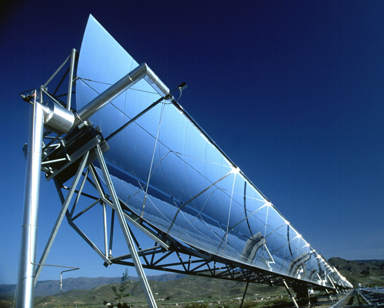
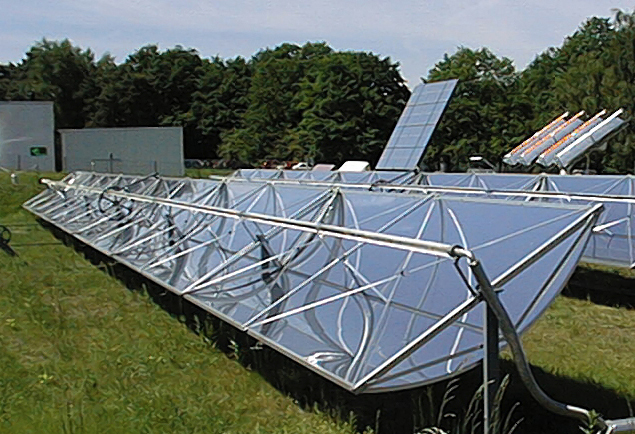
parabolic solar trough concentrator in a solar power station (photos with kind permission of DLR/Cologne)


  • with quartz controlled calendar clock
  • auto protocol function
  • auto start after power failure
  • most comfortable in installation and operation
  • superior to integrate into existing equipment
  • single axis operation also
  • horizon-to horizon operation (AZ up to 360° & EL up to 90°)
  • resolution of max. 65,000 steps, each axis
  • low-voltage version (for buffered battery operation) (optional)
  • control for heavy rotor motors (e. g. 3-phase models) and monster
  • astronomic-mathematical program
  • with wind-sensor-interface
  • with load/power-depending position-optimizing (optional)
  • thereby the modes "autofocus" and "autotracking" can be performed
  • RS-232C interface (optional)
  • 19" rack mount version (optional)
  • manuals in English language!


Energy gathering out of an inexhaustible reserve. Deflect energy. Concentrate energy in focus. Collect energy without cost collects over years – easier, more comfortable, more effective!

And increasing energy (comparison between yield – power). Get knowledge and recognize the sun in science, research and education by precise positioning, and easy – comfortable probe tracking!


Photo 11 Photo 12 Photo 13
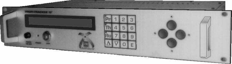
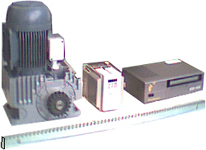
computer with display (desktop version) controlpanel in 19" rack mount (2 HE)

(dimensions (W x H x D): approx. 484 x 88 x 255 mm)
connectors (connecting
cables for Wind-Sensor
and Analog-Input are
included)
DISPLAY-READOUT
  operation status   mode   time   activity   day cycle   azimuth angle   elevation angle  
               
  RUN   M   15:34:48   Go   S   AZ123.5   EL015.2  
CAUTION: Not all function are available on all versions and for each operating mode.


The indoor unit consists out of a complete computer with rotor power supply. These electronics are established in a metal casing with front sided operating elements and a 40 digit LC-Display (image B). On the rear you will find the connection-clamps for the cable serving the rotor and the connectors for RS 232 C-interface and analog input, and the wind sensor interface as well (image G).

Task of the system: direct, synchronized following and tracking the sun's course. The drive and therewith the object mounted onto the gear (solar-collectors, photovoltaik-panel, parabolic or spherical collector, radio measuring sonde etc.) are looking "directly" into the sun. This direct-tracking is implemented in this system very easily, but as well you can achieve a targeted, precise "offset".


BASIS VERSION back to the beginning


Basis version:


SOLAR-AUTO-CONTROLLER

is a micro-processor-guided controller which contains the positioning logic as well as the power unit for the relais and also for smaller motors. It is possible to drive two seperate relais/motors (max 2.5 A/axis) with dual backfeed-pulse-sensors – one for the elevation axis, one for the azimuth axis. The relais/motors are actuated by relais (semiconductor-version on request).
The positioning procedures onto the sun are calculated with a comprehensive astronomical program. Therefor the Kepler data of sun and earth as well as date and time and the system's location have been involved.

Features:

  • with up to 90 degrees elevation-swing
  • with up to 360 degrees azimuth turn angle
  • with 40 characters LC display
  • with lots of dynamic operational information in the display:
  • mode
  • time
  • optional analog-level     
  • date
  • AZ-angle     
  • and many more     
  • direction of move
  • EL-angle
  • with quartz controlled calendar clock
  • with programmable angle limits
  • with battery-backed buffered memory
  • with auto-start after mains failure
  • with wind-sensor-interface

The complete control is implemented in the frontsided key panel (image B).
This device can be delivered for use with 230/115 V AC or 24 V DC.

Motor-/Gear requirements:

  • linear feedback pulse for movement angle ratio (Optional by a collecting system for nonlinear "feedback pulse for movement angles" can be provided.)
  • dual bipolar feedback pulse system
  • feedback pulse frequency: max. 200 Hz
  • feedback pulse length: min. 2.5 mSek.
  • max. resolution: 65000 pulses/axis (speak with us about the choice for a resolution!)
  • one orientation-switch per axis

Installation sequence: When mounting the load to be positioned mechanically (PV-panel, collector, measuring sonde etc.), the mechanical assembly has to be aligned roughly into the north-south direction only. Merely 4 parameters are to be entered after that:
1. The motor's "pulse to movement angle ratio".
2. The geographical coordinates of the installations location (longitude and latitude).
3. Time and date (UT). (The consideration of leap-years, the true local time calculation and the calculation of the sun-coordinates are performed full-automatically. Any re-adjustment of the internal clock is not required, when the time shifts from summertime to wintertime).
4. Tracking-frequency/-intervals or tracking-angles selection (max. allowable angle-deviation).
The load to be positioned now is turned/driven directly into the sun-optimum with the four keys (UP/DOWN/EAST/WEST).
Installation completed.

After starting the system follows the sun day by day – completely automatic. If the sun leaves the angle-limits set by you, the rotor waits in his night-inoperative position for the next day and starts again his daily work in the right moment and at the right spot.
To use the rest-light after sunset, the user determinates, how long the system holds out in this position after sunset. This happens correspondingly at sunrise. Equally any park/night position can be programmed freely.

By clever setting the max. allowable angle-deviation or the next search-cycle, the system can be influenced motor sparing.
Of course, you may drive to any desired position with such a system: Look at the display, watch AZ- and EL-angle; push – right-left – up-down – as you like. Min. step size 0.1°!

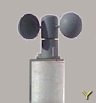
Wind-sensor-pulses can be transmitted to the control logic via the wind-sensor-interface for an automatic evaluation. This is used to drive to a programmable motor-/gear-position automatically, when a selectable wind speed threshold is exceeded (image G)!

If the control system should drive the 24 V DC motors directly, a semiconductor-relais-version instead of mechanical relais can be delivered. This version then allows:

  • softer starting and stopping of the motors
  • no loss of contact due to contactless mechanical switching
  • less vulnerable to operational interruptions due to no switching or tear off spark formation
  • noiseless control device due to no movable parts
  • accomplished two-speeds-operation, because semiconductors can be switched on and off highfrequently,
  • because it is possible to drive different speeds using semiconductor switches


EXTENSIONS & OPTIONS back to the beginning


O

DC 12 V

Electronic voltage conversion from 12 V DC to 24 V DC. The SolarAutoController can be operated between 12 V up to 20 V with this option.


O

ANALOG-INPUT

This hard and firmware allows to feed an extern analogous signal into the control box on the rear side (image G). This signal is processed with 8 bit solution (0 until 255) and serves to the automatic position-optimization.

Typical uses are:

  • a temperature dependent solar collector slaved control and/or optimization
  • charge and voltage dependent photovoltaik panel tracking and/or optimization
  • a light (lux) dependent position optimization of optical lenses/collectors
  • and many more!

The demanded DC voltage should be within the area between 0.2 until 12 Volt. The input impedance is around 250 kOhm. As well as positive indicated signals as well as reciprocal signals can be processed. The operational area of the measured signal can be adapted to the probe as well as in amplitude/slope as well as in setting zero (signal var. 0.1 V pos/neg). The sampling input clockrate is about 250 Hz!
By this procedure signal performance is achieved never managable by hand.
If wanted this signal values can be interrogated via the RS 232 C interface separately – or automatically/cyclically. By use of the keys of the control box an optimization process can be started anytime (or with the sequence of letters "FOCUS" via data-interface). The optimization and tracking behavior can be influenced motor-saving itself by programming of the admissible signal break level (threshold) by selection of the next test cyclus timing, by determination of the signal amplitudes and by determination of the search algorithm. The pluggable connection cable to the probe is inclusive in delivery.


O

Photo 13

DATA-INTERFACE

The 'SolarAutoController' can be connected to an external computer for communication using a two way »RS 232 C data interface« (datastream: 8 bit/no parity/1 stop-bit/300 up to 76800 baud with/without hardware-handshake).
The direction determining information are given via "RS 232 C" interface into the rotor-control. Likewise in opposing direction information can be loaded out of operational status. The intelligent interface allows operation via phone modem too.
When working together with the option "analog-interpretation" the system can be used for the analog signal controlled aligning and tracking of probe signals e. g. weather balloons. The measuring directions and the analog power values are transfered via the data interface onto the external computer permanently!
The communication between control box and external computer is managed in a kind of BASIC language, by which only the simple 7 bit ASCIl mode is used.

Command syntax examples:

  • Turn azimuth-motor on 134.56°   –   "AZ = 134.56 [CR]"   or
  • Command computer elevation position   –   "EL = ? [CR]"
  • Using the instruction-word "FOCUS" automatically starts an focussing-run.
  • Using the instruction "RESULT", after each auto-focussing the automatic output of operational and performance data is induced, e. g. AZ- and EL-angle with corresponding fieldstrength. These can be transferred to a computer (as a protocol for instance), but also onto a printer directly! These data can be stored on the computer's hard disk in a file and can be used in any commercially available spreadsheet program (MS Excel etc.) or in data bases and can be displayed graphically without a special program!
    The version 'SolarAutoController with semiconductors' is inserting date and time into this data string additionally. See a sample of this data string here:
    Row-no.; day; date; time; tracking-channel; AZ-angle; EL-angle; AZ-motor-pulses; EL-motor-pulses; level of analog-channel 1; 3; 4 in the format as follows: 00000 Mon 11.12.98 15:23:44 01 00000 00000 00000 00000 00000 00000 00000.
    This data can be transferred to a modem also! Built-in filters allow a multi rotor operation at a single interface. (Not all applications have yet been discovered. What's your idea: …?)

Already with any simple terminal program commands and responds can be managed via modem and wire!

This interface is needed to extend with the "GPS CAPTURE".


O

GPS CAPTURE FUNCTION   (only in combination with Data-Interface)

By this function you may take over global positioning data automatically from a GPS navigator/receiver via the serial interface into program-memory PRG 01 of the control unit.

The NMEA183 protocol with data set "GPRMC" will be used.


O

Photo 12

GR-19

For control centers and technical headquarters in weather observatories, universities, research laboratories and scientific institutes service and control often is demanded in 19" racks. With this option the mounting of the standard SolarAutoController into a 19" rack with 2 HE x 290 mm with aluminum-colored front board is available. Additional to better EMC a pluggable wiring and an illuminated two-lined displays is included in the price. Likewise a frontsided security lock (2 keys) to lock definite operating functions is provided which secures the station against inadmissible operation. Accessory LEDs show run-directions and different operational status. Furthermore the device offers the possibility to operate the motor unit via an additional interface with lower or higher voltage/power (limited) too for speed-control and/or increased power. That surrenders also an advantageous separation of the power-supply of logic and power!


O

Photo 144

LIGHT DIRECTION FINDING TUBE

The light-direction/calibration tube allows the easy and comfortable finding of the direction/position with the maximum of light. It consists out of a inside matted tube with a sensor attached at the tube-base bottom. A 5 m long litz wire is connected solidly. Attached are a universal sensor-fix and mounting-material.

The tube carrier has to be mounted plane onto the object to be positioned, so that the direction finding tube stands perpendicular upright on the sight-plane. The direction finding device can be connected to any ohm-meter (multimeter) usual in the trade and serves in this application to manually align the rotor-head with the keys on the control-unit (UP/DOWN/EAST/WEST). A fully automatical position-optimization is possible along with the device-extension "ANALOG"-signal-input. Thereby signal-peaks are achieved, not manageable in manual operation. In the mode "AUTOFOCUS" – automatically – after each astronomical positioning an investigation for a better signal is originated. The results are displayed with a 8 bit word in the control-unit`s display and output via the serial interface together with other data, if needed.


O

Photo 152

WIND-SPEED-SENSOR/SHELL-ANEMOMETER

The Anemometer performs the measurement of the local appearing wind-speeds. The 4-wire-interface at the control unit is quite ready to read and process the signals from the anemometer.

Details:

  • 3-shell-system
  • shell ring outside-Ø: 120 mm
  • shell-Ø: 40 mm
  • profile: 70 mm
  • material: ABS
  • pulse transducer system: magnet/reed switch
  • pulse-rate: 60 km/h = 16.8 m/sec. = 47 Hz
  • suitable for mounting onto or besides the mast


Photo 116 Photo 144 Photo 152 Photo 187
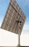
Both gear transmission as well as linear drive can go into action. light direction
finding tube
shell-anemometer Heliostat


SPECIFICATIONS back to the beginning


OPERATIONAL COMPUTER:   EPS-103 mod. Solar
power supply 223/115 Volt AC 16 Watt standby (100 Watt max.) or
24 Volt DC 1 Watt Standby (100 Watt max.)
12 Volt DC (optional)
motor control 24 Volt DC / max. 2.5 Amp.
pulse frequency max. 200 Hz
pulse width min. 2.5 msec.
resolution max. 65,000 pulses/axis


PRICE LIST back to the beginning


VERSION | (excl. VAT) EURO
SolarAutoController bi axial solar positioning control for gear motors 2 343.00


OPTIONS | (excl. VAT) EURO
DC 12 V 12 V power supply for DC 24 V version 478.35
ANALOG-Input analogous signal-dependent positioning load/power dependent 748.00
Data-Interface Hard- & software extention RS 232 C interface 798.00
GPS interface GPS software interface 549.00
is only supplied in combination with Data-Interface
GR-19 basis unit fitted into a 19" rack mount (2 UH) 998.00
Li-SP1 for the easy and comfortable finding of the direction/position with the maximum of light 378.00
Wi-S1 wind-speed-sensor/shell-anemometer 317.35


Please tell us about your particular special application!


Technical improvements are subject of change!


      CONTENT:   basis version | extensions | specifications | price list     


EGIS Cloud


EGIS-Logo E       G       I       S
EQUIPMENT GESELLSCHAFT für
INTERN. ELEKTRONIK SYSTEME GmbH
Flutstraße 34 – 36
D–63071 OFFENBACH/MAIN
Tel.: 069 / 85 83 27
Fax: 069 / 85 78 63
<< Homepage 20 minutes from Airport Frankfurt – 20 minutes to Frankfurt City E-Mail: Solar@egis.eu